

Guided Weapons

Centred on the guidance & control unit, Digitron develops and produces the core electronics of guided-weapon systems — guidance data receivers, actuation controllers, anti-jam GNSS RF assemblies, fuze TDD signal processors, and seeker frequency synthesizers and servo controllers. We also supply the command & communication device and code loader that support weapon employment, and guidance & control units for aerial target drones.
Guidance & Control Unit (GCU)
The brain of the round: it links the forward subsystems — seeker, IMU, guidance data receiver — with the aft subsystems — actuation unit, anti-jam GNSS, fuze — and controls every phase of flight.
Guidance & Control Unit — Operating Concept
Inside a guided-weapon system the guidance & control unit exchanges power, commands and target data with the forward and aft subsystems, controlling the round through every phase of flight. The diagram magnifies the position of the unit within the round and shows the signals exchanged with each subsystem.
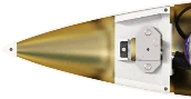 Nose Cap
- Incoming signalNose-cap separation signal
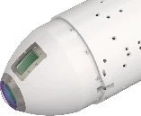
- Incoming signalPower, target data, commands
- Outgoing signalTarget data, track & detection data
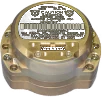 Inertial Measurement Unit
- Outgoing signalAcceleration, angular rate
- Incoming signalPower, clock
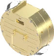
- Incoming signalPower, commands
- Outgoing signalTarget data, mission data
- Two-way signalDrive commands, responses, status
- Incoming signalPower
- Outgoing signalGNSS data, status
- Incoming signalPower, commands
 Flight Measurement Unit
- Incoming signalIn-round data, power
- Incoming signalDetonation signal, delay data
- Outgoing signalStatus data

Guided-rocket configuration — the marked band is where the guidance & control unit sits
130 mm Guided Rocket-Ⅱ Guidance & Control Unit
01High-performance computing and control
DSP- and FPGA-based data-processing architecture and memory system
Multiple communication interfaces
High-speed, high-reliability interfaces across serial, industrial-network and Ethernet standards
Signal processing and circuit design
Multi-channel signal-control circuits with FPGA-integrated communication channels
System health monitoring and protection
Real-time temperature and voltage monitoring, with protection circuits for discrete I/O signals
EA Guidance & Control Unit (Export)
In productionHigh-performance control and data processing
DSP- and FPGA-based digital signal processing and memory control
Reliable communication interfaces
Industrial CAN and multi-channel serial (RS-422) communication modules
Hardware optimisation
Multiple PCBs integrated into a single board for maximum space efficiency and productivity
Commercial results
Development completed and series production established
L-SA* Guidance & Control Unit
03High-performance computing and control processing
DSP- and FPGA-based data-processing architecture with a high-speed memory system
Multiple communication interfaces
Reliable communication modules for serial (RS-422, UART), Ethernet and CAN
Signal control and logic design
Multi-channel signal-control circuits with FPGA-integrated communication channels
Health monitoring and circuit protection
Real-time temperature and voltage monitoring, with protection circuits for discrete I/O signals
REDEYE Guidance & Control Unit (Export)
04Thermal management and reliability
Heat-dissipation design for efficient heat spreading and thermal management
Multiple communication interfaces
Wired and high-speed communication control across a range of standard interfaces
Signal processing and logic design
Multi-channel signal-control circuits with communication channels integrated in programmable logic
Real-time monitoring interface
Real-time temperature and voltage-level sensing to track system status
Signal control and circuit protection
Discrete-signal I/O control and protection circuits for system stability
Ship-** Ⅱ Guidance & Control Unit
05Thermal management and heat-dissipation structure
Heat-dissipation design for efficient heat spreading and stable operation
Multiple communication interfaces
Control and implementation of wired, high-speed and standard serial interfaces
Signal control and logic circuit design
Multi-channel signal-control circuits with communication channels integrated in programmable logic
Real-time system monitoring
Real-time temperature and voltage-level sensing and monitoring of the operating environment
Signal I/O and circuit protection
Discrete-signal I/O control and protection circuits against over-voltage and signal interference
Guidance Data Receiver (Weapon Datalink Modem)
MPSOC- and RFSOC-based signal-processing boards and 1T3R modem platforms that let the round receive target and mission data from the ground or shipboard control station in real time.
Guidance & Control Unit — Operating Concept
Inside a guided-weapon system the guidance & control unit exchanges power, commands and target data with the forward and aft subsystems, controlling the round through every phase of flight. The diagram magnifies the position of the unit within the round and shows the signals exchanged with each subsystem.
Nose Cap- Incoming signalNose-cap separation signal
- Incoming signalPower, target data, commands
- Outgoing signalTarget data, track & detection data
Inertial Measurement Unit- Outgoing signalAcceleration, angular rate
- Incoming signalPower, clock
- Incoming signalPower, commands
- Outgoing signalTarget data, mission data
- Two-way signalDrive commands, responses, status
- Incoming signalPower
- Outgoing signalGNSS data, status
- Incoming signalPower, commands
Flight Measurement Unit- Incoming signalIn-round data, power
- Incoming signalDetonation signal, delay data
- Outgoing signalStatus data
Guided-rocket configuration — the marked band is where the guidance data receiver sits
L-SA* Modem Board
In productionL-SA* modem platform development
Modem platform development
Modem-board system platform for high-performance communication
High-performance signal-processing design
Integrated digital and RF signal-processing board built on a multi-function processor
RF transceiver architecture
Multi-channel RF transmit/receive architecture
Commercial results and production
System development completed and series production established
Short-Range Air-to-Air Modem Board
In developmentShort-range air-to-air modem platform development
Airborne communication modem platform
Modem-board system dedicated to short-range air-to-air communication
High-performance RF signal-processing board
Domestically developed signal-processing board integrating RF and digital processing
Multi-channel RF transceiver architecture
Multi-channel RF transmit/receive architecture
Development status
Localisation and core-technology development in progress
Ship-** Ⅱ Modem Board
In developmentShip-** Ⅱ modem and weapon-datalink platform development
Guided-weapon modem platform
Modem-board system platform for the next-generation surface-to-air guided-weapon system (Ham**-Ⅱ)
High-performance signal-processing design
Integrated digital and RF signal-processing board built on a multi-function processor
Multi-channel RF transceiver architecture
Multi-channel RF transmit/receive architecture for stable data transfer
Development status
Core technologies implemented; development in progress
L-SA*-Ⅱ Modem Board
In developmentL-SA*-Ⅱ modem and weapon-datalink platform development
Guided-weapon modem platform
Modem-board system platform for the next-generation long-range surface-to-air guided-weapon system (L-SA*-Ⅱ)
High-performance signal-processing design
Integrated digital and RF signal-processing board built on a multi-function processor
Multi-channel RF transceiver architecture
Multi-channel RF transmit/receive architecture for stable data transfer
Development status
Core technologies implemented; development in progress
MSA*-Block-Ⅲ Modem Board
In developmentMSA*-Block-Ⅲ modem platform development
Guided-weapon modem platform
Modem-board system platform for the next-generation medium-range surface-to-air guided-weapon system (MSA*-Block-Ⅲ)
High-performance signal-processing design
Integrated digital and RF signal-processing board built on a multi-function processor
Dual-band RF transceiver architecture
Flexible RF transmit/receive architecture supporting multiple frequency bands and channels
Development status
Core technologies implemented; development in progress
Actuation Unit (Actuator Controller)
The actuation-unit circuit-card assembly: it takes drive commands from the guidance & control unit, generates the drive output for each actuator axis, and measures actuator status.
Guidance & Control Unit — Operating Concept
Inside a guided-weapon system the guidance & control unit exchanges power, commands and target data with the forward and aft subsystems, controlling the round through every phase of flight. The diagram magnifies the position of the unit within the round and shows the signals exchanged with each subsystem.
Nose Cap- Incoming signalNose-cap separation signal
- Incoming signalPower, target data, commands
- Outgoing signalTarget data, track & detection data
Inertial Measurement Unit- Outgoing signalAcceleration, angular rate
- Incoming signalPower, clock
- Incoming signalPower, commands
- Outgoing signalTarget data, mission data
- Two-way signalDrive commands, responses, status
- Incoming signalPower
- Outgoing signalGNSS data, status
- Incoming signalPower, commands
Flight Measurement Unit- Incoming signalIn-round data, power
- Incoming signalDetonation signal, delay data
- Outgoing signalStatus data
Guided-rocket configuration — the marked band is where the actuation unit sits
MSA*-Block-Ⅲ Actuator Controller
01Actuation-unit circuit-card assembly
Integrated actuator control and computation
Actuator status measurement, real-time control computation and signal generation
Multi-axis drive output
Dedicated drive outputs for multi-axis actuators
Inter-module signal interface
Stable signal connection between circuit cards and peripheral units
Stable power supply
Supply and distribution of the power the controller needs
Anti-Jam GNSS RF Assembly
Guidance & Control Unit — Operating Concept
Inside a guided-weapon system the guidance & control unit exchanges power, commands and target data with the forward and aft subsystems, controlling the round through every phase of flight. The diagram magnifies the position of the unit within the round and shows the signals exchanged with each subsystem.
Nose Cap- Incoming signalNose-cap separation signal
- Incoming signalPower, target data, commands
- Outgoing signalTarget data, track & detection data
Inertial Measurement Unit- Outgoing signalAcceleration, angular rate
- Incoming signalPower, clock
- Incoming signalPower, commands
- Outgoing signalTarget data, mission data
- Two-way signalDrive commands, responses, status
- Incoming signalPower
- Outgoing signalGNSS data, status
- Incoming signalPower, commands
Flight Measurement Unit- Incoming signalIn-round data, power
- Incoming signalDetonation signal, delay data
- Outgoing signalStatus data
Guided-rocket configuration — the marked band is where the anti-jam gnss unit sits
Common features
GPS receiver able to operate under attack from external jamming systems
- Low-noise amplifier design
- Phase-noise minimisation through reference-oscillator design
- Multi-channel / multi-band implementation and miniaturisation design
- Frequency up/down conversion and digital signal conversion design
- Digital-noise suppression through power-rail isolation
L-SA* Anti-Jam GNSS RF Board
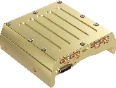
01Shielded board with eight RF connectors and a high-density signal connector
L-SA*-Ⅱ Anti-Jam GNSS RF Board
02Next-generation RF board built on the L-SA* RF-board platform
Long-Range Air-to-Ground GNSS RF Board
03Housing-integrated RF assembly with side-mounted RF ports
Ship-** Missile Ⅱ GNSS RF Board
04Compact housing with integral mounting lugs and compartmented shielding
Fuze TDD Signal Processor
The signal processor of the target-detection device (TDD) that determines the point of closest approach and issues the detonation signal — demanding both very high-speed digital signal processing and high-reliability power and monitoring design.
Guidance & Control Unit — Operating Concept
Inside a guided-weapon system the guidance & control unit exchanges power, commands and target data with the forward and aft subsystems, controlling the round through every phase of flight. The diagram magnifies the position of the unit within the round and shows the signals exchanged with each subsystem.
Nose Cap- Incoming signalNose-cap separation signal
- Incoming signalPower, target data, commands
- Outgoing signalTarget data, track & detection data
Inertial Measurement Unit- Outgoing signalAcceleration, angular rate
- Incoming signalPower, clock
- Incoming signalPower, commands
- Outgoing signalTarget data, mission data
- Two-way signalDrive commands, responses, status
- Incoming signalPower
- Outgoing signalGNSS data, status
- Incoming signalPower, commands
Flight Measurement Unit- Incoming signalIn-round data, power
- Incoming signalDetonation signal, delay data
- Outgoing signalStatus data
Guided-rocket configuration — the marked band is where the fuze sits
Ship-** Ⅱ Fuze TDD Signal Processor
01Ultra-high-speed signal processing and algorithms
High-performance signal-processing circuits for real-time handling of large data volumes and complex algorithms
High-speed data interfaces
Serial interfaces optimised for fast, stable transfer of large data between the core compute modules
Signal integrity and noise control
Advanced routing and board design that preserve high-speed signal quality and minimise analogue noise
High-reliability power management and protection
Stable power distribution with input-protection circuits that prevent system damage
Real-time health monitoring
Real-time sensing and monitoring of voltage, current and temperature for safe operation
Hae* Fuze TDD Signal Processor
02High-speed RF signal processing and logic
Logic optimised for real-time computation on RF signals and high-speed digital signal processing
High-efficiency power management and conversion
Miniature, high-efficiency power conversion and noise-filtering circuits for stable communication and control modules
High-speed, low-latency internal interfaces
Real-time, high-speed, low-latency data links between the core control components
Real-time health monitoring
Real-time sensing and remote monitoring of voltage, current, temperature and output status for system reliability
Seeker (Frequency Synthesizer)
Guidance & Control Unit — Operating Concept
Inside a guided-weapon system the guidance & control unit exchanges power, commands and target data with the forward and aft subsystems, controlling the round through every phase of flight. The diagram magnifies the position of the unit within the round and shows the signals exchanged with each subsystem.
Nose Cap- Incoming signalNose-cap separation signal
- Incoming signalPower, target data, commands
- Outgoing signalTarget data, track & detection data
Inertial Measurement Unit- Outgoing signalAcceleration, angular rate
- Incoming signalPower, clock
- Incoming signalPower, commands
- Outgoing signalTarget data, mission data
- Two-way signalDrive commands, responses, status
- Incoming signalPower
- Outgoing signalGNSS data, status
- Incoming signalPower, commands
Flight Measurement Unit- Incoming signalIn-round data, power
- Incoming signalDetonation signal, delay data
- Outgoing signalStatus data
Guided-rocket configuration — the marked band is where the seeker sits
Common features
Frequency signal generator for precision target detection
- High-resolution design using DDS
- Vibration-tolerant low-phase-noise design
- LFM and HRR waveform generation design
- High-speed switching design
- Ku-band RF signal generation design
Cheon*-Ⅰ Frequency Synthesizer
01Single shielded housing with three RF connectors
Cheon*-Ⅱ Frequency Synthesizer
02Housing with multiple shielded cavities
Hae* Frequency Synthesizer
03Two-unit set: reference signal generator and synthesizer body
L-SA* Frequency Synthesizer
04Multi-cavity shielded structure with side-mounted RF ports
Seeker (Servo Controller)
Servo controllers that stabilise the line of sight of imaging seekers.
L-SA*-Ⅱ Imaging Seeker Servo Controller
01Servo-control circuit-card assembly driving the imaging-seeker gimbal
- BiSS-C/SSI encoder interface design
- RS-422/RS-232 communication interface design
- PMSM servo-motor current control
- Isolated phase-current feedback circuit design
- Isolation circuit design between the control and drive stages
- Temperature and voltage-level monitoring interface design
- Discrete-signal I/O and protection circuit design
Weapon Employment Support Equipment · Aerial Target Drone
Cockpit and portable equipment that supports weapon employment, together with the guidance & control unit of an aerial target drone: the command & communication device that transmits the mission to an air-launched guided munition from the cockpit, the code loader that loads and transfers crypto codes, and the GCU of the supersonic cruise target drone used in air-defence live-fire training.
Command & Communication Device — Air-Launched Guided Munition (Domestic / Export)
In productionHost aircraft: F-5E/F, F-15K, F-4E, (K)F-16C/D, FA-50
- Real-time computation and display of the release area from aircraft latitude, longitude, altitude and speed
- Optimised map rendering
- Day and night GUI skins, with four-step LCD backlight control for night operation
- One-touch mission erase for pilot safety in an emergency
- Compliant with the defence map-symbol standard MND-STD-0023A-02
- Compliant with DAPA weapon-system software development and management regulations
OOO Code Loader — OO System OOOO Upgrade
02- Performs code-loader and code-transfer functions, with OOOO operating-concept setting
- Consolidates the separate code-entry and code-transfer accessories into a single device
- FPGA-linked protocol design for sharing codes between code loaders
- Security design that erases the codes automatically on disassembly or battery depletion
Supersonic Cruise Aerial Target Drone GCU (Domestic / Export)
03Power management and drive control
Stable multi-channel power supply with built-in BLDC motor drive and Hall-sensor input circuits
High-performance processing and system control
DSP- and FPGA-based processing for communication with, and integrated control of, the internal components
Signal processing and I/O control
Multi-channel I/O control, constant-current control outputs, analogue signal processing and protection circuits
Communication and interfaces
Multi-channel communication interfaces across serial, Ethernet and other standards
Real-time system monitoring
Real-time temperature and voltage-level monitoring for a stable operating environment