

Business
We develop and supply core electronics for guided weapons, surveillance, avionics, aviation lighting, AI and EW/communications — and productise the same core technologies as commercial modules.
Centred on the guidance & control unit, Digitron develops and produces the core electronics of guided-weapon systems — guidance data receivers, actuation controllers, anti-jam GNSS RF assemblies, fuze TDD signal processors, and seeker frequency synthesizers and servo controllers. We also supply the command & communication device and code loader that support weapon employment, and guidance & control units for aerial target drones.
Guidance & Control Unit (GCU)
The brain of the round: it links the forward subsystems — seeker, IMU, guidance data receiver — with the aft subsystems — actuation unit, anti-jam GNSS, fuze — and controls every phase of flight.
Guidance & Control Unit — Operating Concept
Inside a guided-weapon system the guidance & control unit exchanges power, commands and target data with the forward and aft subsystems, controlling the round through every phase of flight. The diagram magnifies the position of the unit within the round and shows the signals exchanged with each subsystem.
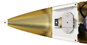 Nose Cap
- Incoming signalNose-cap separation signal
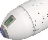
- Incoming signalPower, target data, commands
- Outgoing signalTarget data, track & detection data
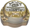 Inertial Measurement Unit
- Outgoing signalAcceleration, angular rate
- Incoming signalPower, clock
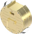
- Incoming signalPower, commands
- Outgoing signalTarget data, mission data
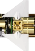
- Two-way signalDrive commands, responses, status
- Incoming signalPower
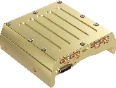
- Outgoing signalGNSS data, status
- Incoming signalPower, commands
 Flight Measurement Unit
- Incoming signalIn-round data, power
- Incoming signalDetonation signal, delay data
- Outgoing signalStatus data

Guided-rocket configuration — the marked band is where the guidance & control unit sits
130 mm Guided Rocket-Ⅱ Guidance & Control Unit
01High-performance computing and control
DSP- and FPGA-based data-processing architecture and memory system
Multiple communication interfaces
High-speed, high-reliability interfaces across serial, industrial-network and Ethernet standards
Signal processing and circuit design
Multi-channel signal-control circuits with FPGA-integrated communication channels
System health monitoring and protection
Real-time temperature and voltage monitoring, with protection circuits for discrete I/O signals
EA Guidance & Control Unit (Export)
In productionHigh-performance control and data processing
DSP- and FPGA-based digital signal processing and memory control
Reliable communication interfaces
Industrial CAN and multi-channel serial (RS-422) communication modules
Hardware optimisation
Multiple PCBs integrated into a single board for maximum space efficiency and productivity
Commercial results
Development completed and series production established
L-SA* Guidance & Control Unit
03High-performance computing and control processing
DSP- and FPGA-based data-processing architecture with a high-speed memory system
Multiple communication interfaces
Reliable communication modules for serial (RS-422, UART), Ethernet and CAN
Signal control and logic design
Multi-channel signal-control circuits with FPGA-integrated communication channels
Health monitoring and circuit protection
Real-time temperature and voltage monitoring, with protection circuits for discrete I/O signals
REDEYE Guidance & Control Unit (Export)
04Thermal management and reliability
Heat-dissipation design for efficient heat spreading and thermal management
Multiple communication interfaces
Wired and high-speed communication control across a range of standard interfaces
Signal processing and logic design
Multi-channel signal-control circuits with communication channels integrated in programmable logic
Real-time monitoring interface
Real-time temperature and voltage-level sensing to track system status
Signal control and circuit protection
Discrete-signal I/O control and protection circuits for system stability
Ship-** Ⅱ Guidance & Control Unit
05Thermal management and heat-dissipation structure
Heat-dissipation design for efficient heat spreading and stable operation
Multiple communication interfaces
Control and implementation of wired, high-speed and standard serial interfaces
Signal control and logic circuit design
Multi-channel signal-control circuits with communication channels integrated in programmable logic
Real-time system monitoring
Real-time temperature and voltage-level sensing and monitoring of the operating environment
Signal I/O and circuit protection
Discrete-signal I/O control and protection circuits against over-voltage and signal interference
Guidance Data Receiver (Weapon Datalink Modem)
MPSOC- and RFSOC-based signal-processing boards and 1T3R modem platforms that let the round receive target and mission data from the ground or shipboard control station in real time.
Guidance & Control Unit — Operating Concept
Inside a guided-weapon system the guidance & control unit exchanges power, commands and target data with the forward and aft subsystems, controlling the round through every phase of flight. The diagram magnifies the position of the unit within the round and shows the signals exchanged with each subsystem.
Nose Cap- Incoming signalNose-cap separation signal
- Incoming signalPower, target data, commands
- Outgoing signalTarget data, track & detection data
Inertial Measurement Unit- Outgoing signalAcceleration, angular rate
- Incoming signalPower, clock
- Incoming signalPower, commands
- Outgoing signalTarget data, mission data
- Two-way signalDrive commands, responses, status
- Incoming signalPower
- Outgoing signalGNSS data, status
- Incoming signalPower, commands
Flight Measurement Unit- Incoming signalIn-round data, power
- Incoming signalDetonation signal, delay data
- Outgoing signalStatus data
Guided-rocket configuration — the marked band is where the guidance data receiver sits
L-SA* Modem Board
In productionL-SA* modem platform development
Modem platform development
Modem-board system platform for high-performance communication
High-performance signal-processing design
Integrated digital and RF signal-processing board built on a multi-function processor
RF transceiver architecture
Multi-channel RF transmit/receive architecture
Commercial results and production
System development completed and series production established
Short-Range Air-to-Air Modem Board
In developmentShort-range air-to-air modem platform development
Airborne communication modem platform
Modem-board system dedicated to short-range air-to-air communication
High-performance RF signal-processing board
Domestically developed signal-processing board integrating RF and digital processing
Multi-channel RF transceiver architecture
Multi-channel RF transmit/receive architecture
Development status
Localisation and core-technology development in progress
Ship-** Ⅱ Modem Board
In developmentShip-** Ⅱ modem and weapon-datalink platform development
Guided-weapon modem platform
Modem-board system platform for the next-generation surface-to-air guided-weapon system (Ham**-Ⅱ)
High-performance signal-processing design
Integrated digital and RF signal-processing board built on a multi-function processor
Multi-channel RF transceiver architecture
Multi-channel RF transmit/receive architecture for stable data transfer
Development status
Core technologies implemented; development in progress
L-SA*-Ⅱ Modem Board
In developmentL-SA*-Ⅱ modem and weapon-datalink platform development
Guided-weapon modem platform
Modem-board system platform for the next-generation long-range surface-to-air guided-weapon system (L-SA*-Ⅱ)
High-performance signal-processing design
Integrated digital and RF signal-processing board built on a multi-function processor
Multi-channel RF transceiver architecture
Multi-channel RF transmit/receive architecture for stable data transfer
Development status
Core technologies implemented; development in progress
MSA*-Block-Ⅲ Modem Board
In developmentMSA*-Block-Ⅲ modem platform development
Guided-weapon modem platform
Modem-board system platform for the next-generation medium-range surface-to-air guided-weapon system (MSA*-Block-Ⅲ)
High-performance signal-processing design
Integrated digital and RF signal-processing board built on a multi-function processor
Dual-band RF transceiver architecture
Flexible RF transmit/receive architecture supporting multiple frequency bands and channels
Development status
Core technologies implemented; development in progress
Actuation Unit (Actuator Controller)
The actuation-unit circuit-card assembly: it takes drive commands from the guidance & control unit, generates the drive output for each actuator axis, and measures actuator status.
Guidance & Control Unit — Operating Concept
Inside a guided-weapon system the guidance & control unit exchanges power, commands and target data with the forward and aft subsystems, controlling the round through every phase of flight. The diagram magnifies the position of the unit within the round and shows the signals exchanged with each subsystem.
Nose Cap- Incoming signalNose-cap separation signal
- Incoming signalPower, target data, commands
- Outgoing signalTarget data, track & detection data
Inertial Measurement Unit- Outgoing signalAcceleration, angular rate
- Incoming signalPower, clock
- Incoming signalPower, commands
- Outgoing signalTarget data, mission data
- Two-way signalDrive commands, responses, status
- Incoming signalPower
- Outgoing signalGNSS data, status
- Incoming signalPower, commands
Flight Measurement Unit- Incoming signalIn-round data, power
- Incoming signalDetonation signal, delay data
- Outgoing signalStatus data
Guided-rocket configuration — the marked band is where the actuation unit sits
MSA*-Block-Ⅲ Actuator Controller
01Actuation-unit circuit-card assembly
Integrated actuator control and computation
Actuator status measurement, real-time control computation and signal generation
Multi-axis drive output
Dedicated drive outputs for multi-axis actuators
Inter-module signal interface
Stable signal connection between circuit cards and peripheral units
Stable power supply
Supply and distribution of the power the controller needs
Anti-Jam GNSS RF Assembly
Guidance & Control Unit — Operating Concept
Inside a guided-weapon system the guidance & control unit exchanges power, commands and target data with the forward and aft subsystems, controlling the round through every phase of flight. The diagram magnifies the position of the unit within the round and shows the signals exchanged with each subsystem.
Nose Cap- Incoming signalNose-cap separation signal
- Incoming signalPower, target data, commands
- Outgoing signalTarget data, track & detection data
Inertial Measurement Unit- Outgoing signalAcceleration, angular rate
- Incoming signalPower, clock
- Incoming signalPower, commands
- Outgoing signalTarget data, mission data
- Two-way signalDrive commands, responses, status
- Incoming signalPower
- Outgoing signalGNSS data, status
- Incoming signalPower, commands
Flight Measurement Unit- Incoming signalIn-round data, power
- Incoming signalDetonation signal, delay data
- Outgoing signalStatus data
Guided-rocket configuration — the marked band is where the anti-jam gnss unit sits
Common features
GPS receiver able to operate under attack from external jamming systems
- Low-noise amplifier design
- Phase-noise minimisation through reference-oscillator design
- Multi-channel / multi-band implementation and miniaturisation design
- Frequency up/down conversion and digital signal conversion design
- Digital-noise suppression through power-rail isolation
L-SA* Anti-Jam GNSS RF Board
01Shielded board with eight RF connectors and a high-density signal connector
L-SA*-Ⅱ Anti-Jam GNSS RF Board
02Next-generation RF board built on the L-SA* RF-board platform
Long-Range Air-to-Ground GNSS RF Board
03Housing-integrated RF assembly with side-mounted RF ports
Ship-** Missile Ⅱ GNSS RF Board
04Compact housing with integral mounting lugs and compartmented shielding
Fuze TDD Signal Processor
The signal processor of the target-detection device (TDD) that determines the point of closest approach and issues the detonation signal — demanding both very high-speed digital signal processing and high-reliability power and monitoring design.
Guidance & Control Unit — Operating Concept
Inside a guided-weapon system the guidance & control unit exchanges power, commands and target data with the forward and aft subsystems, controlling the round through every phase of flight. The diagram magnifies the position of the unit within the round and shows the signals exchanged with each subsystem.
Nose Cap- Incoming signalNose-cap separation signal
- Incoming signalPower, target data, commands
- Outgoing signalTarget data, track & detection data
Inertial Measurement Unit- Outgoing signalAcceleration, angular rate
- Incoming signalPower, clock
- Incoming signalPower, commands
- Outgoing signalTarget data, mission data
- Two-way signalDrive commands, responses, status
- Incoming signalPower
- Outgoing signalGNSS data, status
- Incoming signalPower, commands
Flight Measurement Unit- Incoming signalIn-round data, power
- Incoming signalDetonation signal, delay data
- Outgoing signalStatus data
Guided-rocket configuration — the marked band is where the fuze sits
Ship-** Ⅱ Fuze TDD Signal Processor
01Ultra-high-speed signal processing and algorithms
High-performance signal-processing circuits for real-time handling of large data volumes and complex algorithms
High-speed data interfaces
Serial interfaces optimised for fast, stable transfer of large data between the core compute modules
Signal integrity and noise control
Advanced routing and board design that preserve high-speed signal quality and minimise analogue noise
High-reliability power management and protection
Stable power distribution with input-protection circuits that prevent system damage
Real-time health monitoring
Real-time sensing and monitoring of voltage, current and temperature for safe operation
Hae* Fuze TDD Signal Processor
02High-speed RF signal processing and logic
Logic optimised for real-time computation on RF signals and high-speed digital signal processing
High-efficiency power management and conversion
Miniature, high-efficiency power conversion and noise-filtering circuits for stable communication and control modules
High-speed, low-latency internal interfaces
Real-time, high-speed, low-latency data links between the core control components
Real-time health monitoring
Real-time sensing and remote monitoring of voltage, current, temperature and output status for system reliability
Seeker (Frequency Synthesizer)
Guidance & Control Unit — Operating Concept
Inside a guided-weapon system the guidance & control unit exchanges power, commands and target data with the forward and aft subsystems, controlling the round through every phase of flight. The diagram magnifies the position of the unit within the round and shows the signals exchanged with each subsystem.
Nose Cap- Incoming signalNose-cap separation signal
- Incoming signalPower, target data, commands
- Outgoing signalTarget data, track & detection data
Inertial Measurement Unit- Outgoing signalAcceleration, angular rate
- Incoming signalPower, clock
- Incoming signalPower, commands
- Outgoing signalTarget data, mission data
- Two-way signalDrive commands, responses, status
- Incoming signalPower
- Outgoing signalGNSS data, status
- Incoming signalPower, commands
Flight Measurement Unit- Incoming signalIn-round data, power
- Incoming signalDetonation signal, delay data
- Outgoing signalStatus data
Guided-rocket configuration — the marked band is where the seeker sits
Common features
Frequency signal generator for precision target detection
- High-resolution design using DDS
- Vibration-tolerant low-phase-noise design
- LFM and HRR waveform generation design
- High-speed switching design
- Ku-band RF signal generation design
Cheon*-Ⅰ Frequency Synthesizer
01Single shielded housing with three RF connectors
Cheon*-Ⅱ Frequency Synthesizer
02Housing with multiple shielded cavities
Hae* Frequency Synthesizer
03Two-unit set: reference signal generator and synthesizer body
L-SA* Frequency Synthesizer
04Multi-cavity shielded structure with side-mounted RF ports
Seeker (Servo Controller)
Servo controllers that stabilise the line of sight of imaging seekers.
L-SA*-Ⅱ Imaging Seeker Servo Controller
01Servo-control circuit-card assembly driving the imaging-seeker gimbal
- BiSS-C/SSI encoder interface design
- RS-422/RS-232 communication interface design
- PMSM servo-motor current control
- Isolated phase-current feedback circuit design
- Isolation circuit design between the control and drive stages
- Temperature and voltage-level monitoring interface design
- Discrete-signal I/O and protection circuit design
Weapon Employment Support Equipment · Aerial Target Drone
Cockpit and portable equipment that supports weapon employment, together with the guidance & control unit of an aerial target drone: the command & communication device that transmits the mission to an air-launched guided munition from the cockpit, the code loader that loads and transfers crypto codes, and the GCU of the supersonic cruise target drone used in air-defence live-fire training.
Command & Communication Device — Air-Launched Guided Munition (Domestic / Export)
In productionHost aircraft: F-5E/F, F-15K, F-4E, (K)F-16C/D, FA-50
- Real-time computation and display of the release area from aircraft latitude, longitude, altitude and speed
- Optimised map rendering
- Day and night GUI skins, with four-step LCD backlight control for night operation
- One-touch mission erase for pilot safety in an emergency
- Compliant with the defence map-symbol standard MND-STD-0023A-02
- Compliant with DAPA weapon-system software development and management regulations
OOO Code Loader — OO System OOOO Upgrade
02- Performs code-loader and code-transfer functions, with OOOO operating-concept setting
- Consolidates the separate code-entry and code-transfer accessories into a single device
- FPGA-linked protocol design for sharing codes between code loaders
- Security design that erases the codes automatically on disassembly or battery depletion
Supersonic Cruise Aerial Target Drone GCU (Domestic / Export)
03Power management and drive control
Stable multi-channel power supply with built-in BLDC motor drive and Hall-sensor input circuits
High-performance processing and system control
DSP- and FPGA-based processing for communication with, and integrated control of, the internal components
Signal processing and I/O control
Multi-channel I/O control, constant-current control outputs, analogue signal processing and protection circuits
Communication and interfaces
Multi-channel communication interfaces across serial, Ethernet and other standards
Real-time system monitoring
Real-time temperature and voltage-level monitoring for a stable operating environment
Through its advanced-technology task force Digitron researches a reinforcement-learning flight-control platform and an imaging seeker running on a domestic NPU, and is extending that work into an AI-based counter-drone interception system built around low-altitude radar and an interceptor drone.
AI Autonomous Control (Reinforcement Learning)
Reinforcement learning — where the agent discovers optimal behavior from rewards alone, without being told the rules or the answer — applied to automatic flight control, on an in-house platform that closes the loop between a repeatable simulation environment and the learning model.
RL Autonomous Control Platform
Advanced R&DA closed-loop learning architecture linking the simulation environment and the RL model through state, reward, and action.
- PyGame-based repeatable test environment providing state and reward in real time
- Seven observations: flight stage · yaw · pitch · tilt · target screen coordinates (dx, dy) · elapsed time (dT)
- Three actions: yaw · pitch · tilt (23 discrete levels each, mapped to angular rates)
- Reward design: per-frame proximity to image center plus terminal hit/miss rewards
- Coordinate system defined by azimuth, elevation, line of sight (LOS), and field of view (FOV)
Flight Scenario Modeling
Advanced R&DA four-stage flight scenario — boost, cruise, synchronize, attack — with terminal decision logic.
- Randomized initial conditions: speed 100–200 m/s · initial pitch −40 to −10° · boost 3–5 s
- Randomized target speed of 30–60 km/h
- Automatic switching of attitude and camera control targets (pitch · tilt) per stage
- Terminal outcomes: HIT · CRASH · loss of lock · MISS
- Training monitor: camera view · map · altitude and attitude graphs
RL Model (PPO)
Advanced R&DActor/Critic policy learning with PPO (Proximal Policy Optimization) on Stable-Baselines3.
- Implemented on Stable-Baselines3, the de-facto standard RL library
- Actor/Critic architecture with two hidden (linear) layers
- Actor [128, 128] · Critic [256, 256] networks
- Convergence analysis comparing learning rates of 0.001 and 0.0003
AI Vision Seeker
Real-time target detection, tracking, and guidance-command generation using a single monocular vision sensor and a domestic NPU — aimed at substantially reducing the weight, power draw, structural complexity, and operating cost of multi-sensor approaches.
Monocular Target Detection & Tracking
Advanced R&DReal-time object detection and target lock-on maintenance from monocular RGB video.
- Bounding-box output from deep-learning detectors (YOLO and MobileNet families)
- Target selected as the detection whose center is nearest the lock-on position
- When objects cross or overlap, the detection closest to the predicted position is kept as the same target
- Loss of lock is declared when the target leaves the frame beyond a set duration
LOS-Based Guidance Control
Advanced R&DConverting image-coordinate error into line-of-sight (LOS) angular error to generate guidance and camera commands.
- Error between target center and image center, normalized by frame size
- Conversion to horizontal and vertical LOS error using HFOV and VFOV
- Real-time generation of vehicle yaw/pitch and camera tilt/zoom commands
- Communication protocol design across simulator, controller, and detector
Domestic-NPU Embedded Inference
Advanced R&DReal-time inference verified on a Raspberry Pi 5 with a domestic DeepX NPU (dx-m1).
- YOLOX-Nano averages 6.5 ms — roughly 10× faster than the same board's CPU (69.2 ms)
- On the NPU: YOLOX-Tiny 8.2 ms · MobileNetV2+SSD 8.4 ms · YOLO26n 19.6 ms
- Benchmarked against PC GPU/CPU environments, confirming embedded real-time feasibility
- Verified against a Unity-based flight simulator — target range 1.5–2.5 km · speed approx. 170 m/s
AI-Based Counter-Drone Interception System
From first detection by the low-altitude radar to autonomous identification, tracking and interception by the interceptor drone — a counter-drone engagement sequence tied together by Digitron's own AI vision algorithms.
Detection, Alerting and Engagement Control
01The hostile loitering munition is first detected 2 km out and the engagement is authorised at the control station.
- Low-altitude radar first detects the intruding loitering munition at 2 km
- Detected threat-track data is transmitted to the control-station system
- The operator confirms the threat on the display and authorises the intercept
- On authorisation the interceptor drone launches toward the predicted target point
AI Target Identification and Tracking
02Digitron's own AI algorithms analyse the interceptor drone's EO camera video in real time.
- The drone begins its manoeuvre and activates its onboard electro-optical camera
- In-house AI algorithms analyse the live EO video stream
- The algorithm identifies the visual signature of the hostile drone
- Real-time detection draws a precise target box, then the system switches to tracking mode
Autonomous Intercept Guidance
03The drone computes its own intercept trajectory from the AI detection data and the target's flight path.
- Optimal intercept trajectory computed onboard from AI detection data and target motion
- Precision guided flight along the computed trajectory to close on the hostile aircraft
- Neutralisation of the loitering munition in the air
Receive, signal-processing and antenna-control assemblies for low-altitude radar, the next-generation short-range air-defence radar and the counter-battery radar Ⅱ, together with compact, lightweight EO/IR signal processors — circuit-card assemblies designed and produced at every level from system to board.
Low-Altitude Radar
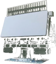
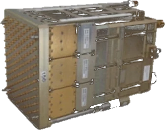
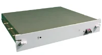
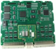
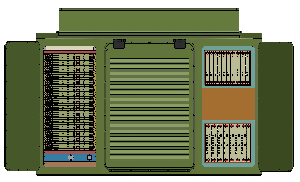
Within the system hierarchy — array antenna and digital-conversion assembly at system level, T/R control assembly at board level — Digitron develops the digital-conversion and transmit/receive control assemblies.
System → Assembly → Board
Digital Conversion Assembly
01- Timing-signal generation design
- HDLC / SPI / UART communication interface design
Transmit/Receive Control Assembly
02- Timing-signal generation, including search-radar transmit timing
- Multi-channel ADC digital-conversion design
- SFPDP interface design for optical signal conversion
- FPDP / SPI / LVDS communication interface design
- Built-in test circuit design for module and unit output signals
Next-Generation Short-Range Air-Defence Radar
Within the hierarchy — receive assembly at system level, multi-channel receive circuit module at board level — Digitron covers multi-channel reception and digital down-conversion.
System → Assembly → Board
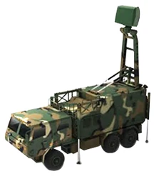 Next-Gen Short-Range Air-Defence Radar
 Receive Assembly
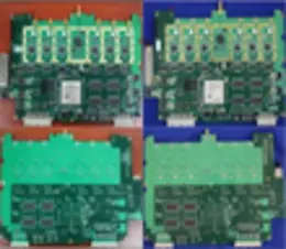
Multi-Channel Receive Circuit Module
01- Receive-path ADC digital-conversion design
- Optical-conversion IP core design
- Optical-transceiver interface transmission design
- S-FPDP / MSPI / LVDS communication interface design
- Digital down-conversion (DDC) design
- Digital filter design
Counter-Battery Radar Ⅱ
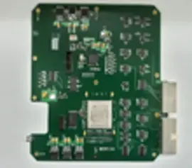
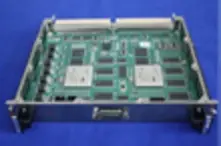
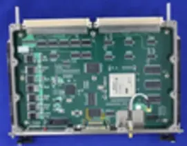
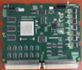
Six circuit-card assemblies spanning the solid-state transmit/receive module, the transmit/receive assembly and the antenna-control assembly.
System → Assembly → Board
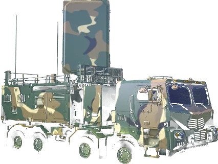 Counter-Battery Radar Ⅱ
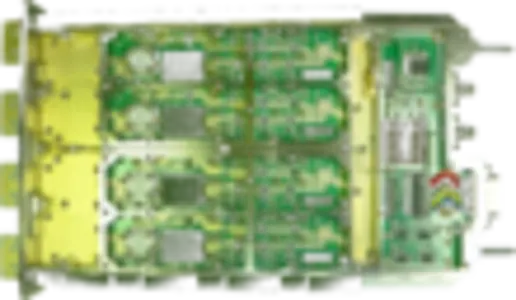 Solid-State T/R Module
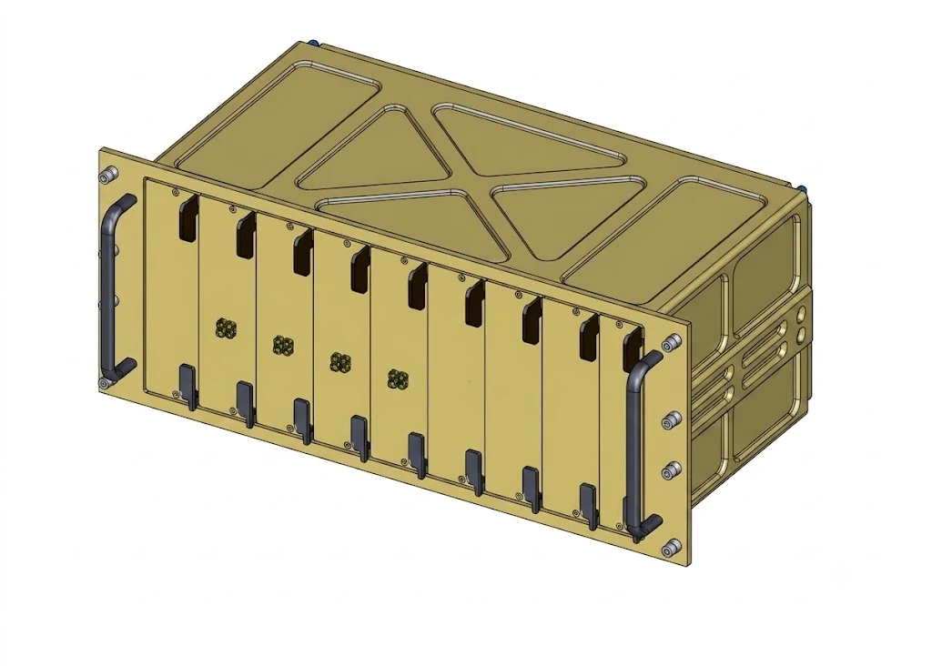 T/R Assembly
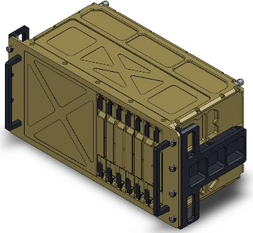 Antenna Control Assembly
Multi-Channel Receive Circuit Module
01- Receive-path ADC digital-conversion design
- Optical-conversion IP core design
- Optical-transceiver interface transmission design
- S-FPDP / MSPI / RS-422 communication interface design
- Digital down-conversion (DDC) and digital filter design
Transmit/Receive Unit Control Module
02- Communication interfaces to the six subordinate modules
- FPGA logic design using a hardware description language
- DSP design for high-speed computation and control
Power Control Circuit Card
03- Power and current monitoring and regulation
- Power sequencing
- Per-channel over-current and over-voltage cut-off
- Safe power switching
Beam-Steering Module
04- Microwave and antenna design
- Phase shifter, high-power amplifier and variable-gain amplifier design
- FPGA logic design using a hardware description language
- DSP design for high-speed computation and control
Antenna Control Module
05- Receive-path ADC digital-conversion design
- S-FPDP optical-conversion communication interface design
- HDLC / SPI / LVDS communication interface design
Antenna Calibration Module
06- Digital signal conversion and digital down-conversion (DDC) design
- SPI / RS-232 communication interface design
- DSP design for high-speed phase-information extraction and control
Electro-Optics (EO/IR)
Sensor-control, signal-processing, cable and temperature-sensor assemblies for compact, lightweight EO/IR signal processors.
Compact, Lightweight EO/IR Signal Processor
01- Sensor control board · thermal-dissipation design
- Sensor control board · Camera Link and Aurora high-speed interface design
- Sensor control board · focus and zoom motor drive design
- Sensor control board · I²C / RS-422 / RS-232 / SPI interfaces and FPGA logic design
- Signal-processing assembly · optical video receive interface and video format conversion
- Elevation cable assembly · flexible PCB design
- Temperature-sensor assembly · sensor monitoring interface design
Store management computers (SMC) for rotary- and fixed-wing aircraft, anti-jam GPS RF assemblies for unmanned aircraft, and AI-compute signal-fusion processors — circuit-card assemblies designed and produced at every level from system to board.
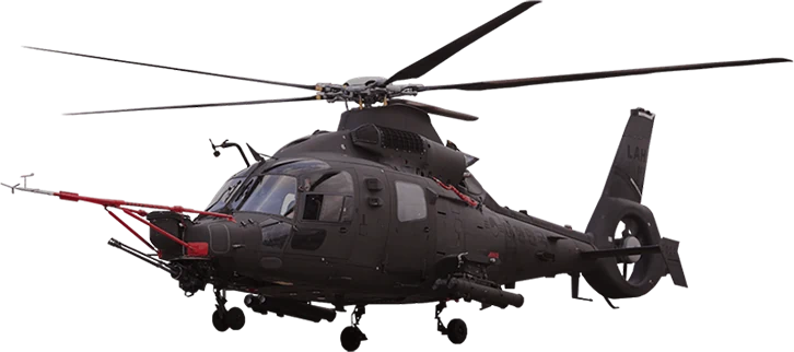
L** SMC (Store Management Computer)
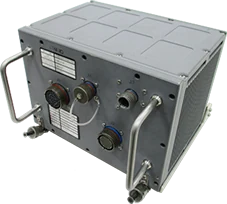
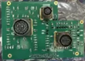
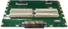
For a rotary-wing aircraft. The computer that controls selection, aiming and release of aircraft stores. Within the breakdown — aircraft, store management computer, circuit-card assemblies — Digitron designs and produces the circuit-card assemblies.
System → Assembly → Board
Transition Module
01- MIL-STD-1553B interface design
- ARINC 429 interface design
- Cut-off frequency design for filtered-connector fabrication
- RS-422 and UART communication interface design
- Protection circuit design against surge and indirect lightning
Motherboard
02- Impedance matching design for high-speed differential signals
- EMI / EMC protection circuit design
K*-** SMC (Store Management Computer)
For a fixed-wing aircraft. The computer that controls selection, aiming and release of aircraft stores. Within the breakdown — aircraft, store management computer, circuit-card assemblies — Digitron designs and produces the circuit-card assemblies.
System → Assembly → Board
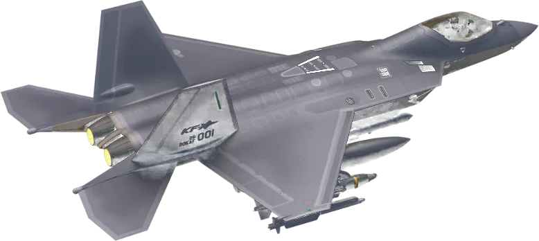 K*-** Series Aircraft
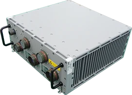 Store Management Computer
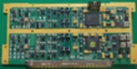
Emergency Jettison / Analogue Module (EJA)
01- Analogue audio circuit design
- Discrete-signal I/O and protection circuit design
- Built-in test circuit design for discrete-signal I/O
- FPGA logic design and timing optimisation using a hardware description language
- Surge and indirect-lightning protection circuit design
- Analogue circuit design for missile launch
- Analogue filter design for noise minimisation
Transition Module
02- MIL-STD-1553B interface design
- ARINC 429 interface design
- Cut-off frequency design for filtered-connector fabrication
- RS-422 and UART communication interface design
- Protection circuit design against surge and indirect lightning
M** SMC (Store Management Computer)
For a rotary-wing aircraft. The computer that controls selection, aiming and release of aircraft stores. Within the breakdown — aircraft, store management computer, circuit-card assemblies — Digitron designs and produces the circuit-card assemblies.
System → Assembly → Board
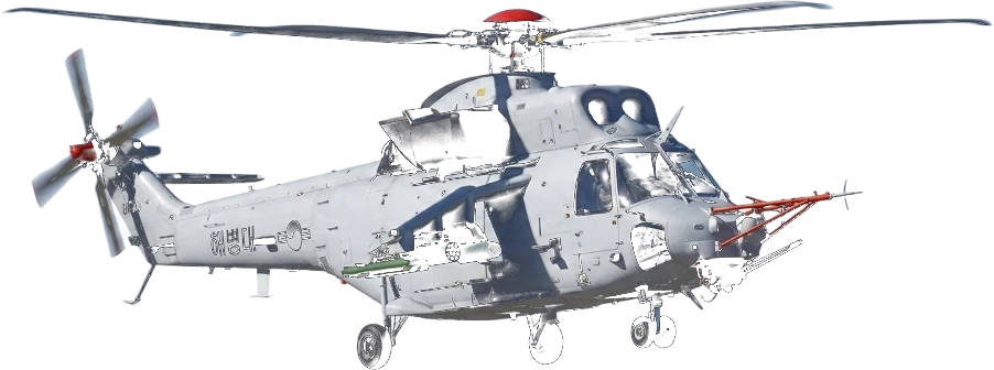 M**-Series Aircraft
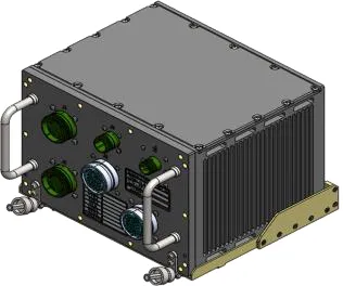 Store Management Computer
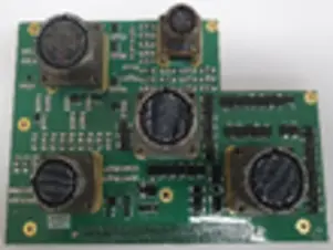
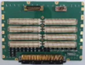
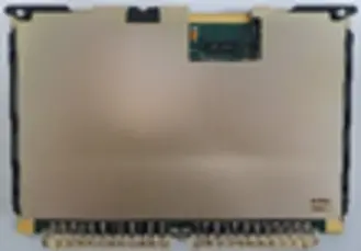
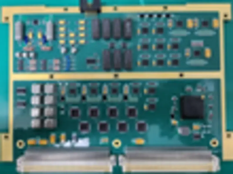
Transition Module
01- MIL-STD-1553B interface design
- ARINC 429 interface design
- Cut-off frequency design for filtered-connector fabrication
- RS-422 and UART communication interface design
- Protection circuit design against surge and indirect lightning
Motherboard
02- Impedance matching design for high-speed differential signals
- EMI / EMC protection circuit design
Store Management Module
03- MIL-STD-1553B interface design
- MIL-STD-1760 mux-bus interface design
- FPGA logic design and timing optimisation using a hardware description language
- DSP design for high-speed computation and control
- RS-232 and RS-422 communication interface design
- Discrete-signal I/O and protection circuit design
Station I/O Module (#1/#2/#3)
04- Video-signal selection output design using an RS-170 mux
- FPGA logic design and timing optimisation using a hardware description language
- Discrete-signal I/O and protection circuit design
- Built-in test design for discrete-signal circuits
Anti-Jam GPS RF Assembly
GPS receiver able to operate under attack from external jamming systems
MALE UAV B6
01GPS receiver able to operate under attack from external jamming systems
- Low-noise amplifier design
- Phase-noise minimisation through reference-oscillator design
- Multi-channel / multi-band implementation and miniaturisation design
- Frequency up/down conversion and digital signal conversion design
- Digital-noise suppression through power-rail isolation
Next-Generation Corps UAV A5
02GPS receiver able to operate under attack from external jamming systems
- Low-noise amplifier design
- Phase-noise minimisation through reference-oscillator design
- Multi-channel / multi-band implementation and miniaturisation design
- Frequency up/down conversion and digital signal conversion design
- Digital-noise suppression through power-rail isolation
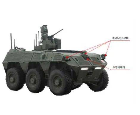
LiDAR–Video Signal Fusion
AI-compute hardware that fuses high-resolution optical camera and LiDAR signals in real time for military unmanned systems.
System → Processor
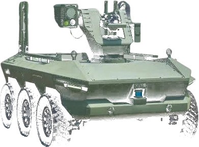 Military Unmanned Ground Vehicle
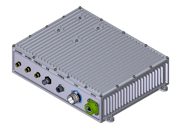
LiDAR–Video Signal Fusion Processor
In development- Synchronisation and fusion of heterogeneous sensor signals
- Integrated SD camera, EO camera, Camera Link and LiDAR interfaces
- Thermal and power design for vehicle installation
Drone Signal-Fusion Processor
An AI-compute board for military unmanned systems (drones and ground vehicles), with an in-house carrier board.
System → Processor
 Military Unmanned Systems (Drone / Ground Vehicle)

Drone Signal-Fusion Processor
In developmentTechnology development for military unmanned systems
- Customisable form factor
- Built-in test function
- In-house carrier board
Korea's first NVIS-compatible aircraft LED lighting systems, developed to MIL-STD-3009 and SAE ARP 5825A and supplied to airworthiness standards as complete interior and exterior lighting sets with controllers.
K** Interior/Exterior Lighting
Interior lighting — general, utility, inspection, cabin and hoist lamps — with exterior formation, anti-collision and position lights, and four power-supply units.
General Lamp (Interior)
01Cockpit dome light — NVIS White interior lighting
- Mounted on the cockpit ceiling to light the whole cockpit
- Switched on and dimmed with its own knob
Utility Lamp (Interior)
02Hand-held, corded utility interior lamp
- Mounted left and right of the overhead console to give the pilot light on demand in flight
- Switched on and dimmed with its own knob
- Coiled cable lets it be taken off its mount and used by hand
Formation Light (Exterior)
03Exterior light for mutual position identification in formation flight
- Mounted on the aircraft exterior
- Shows the attitude and position of the aircraft to the trailing pilot in night formation flight
Anti-Collision Light (Exterior)
04High-intensity dual-colour (white/red) anti-collision light
- Mounted on the upper and lower fuselage to prevent collisions between aircraft
- Flashes 40–100 times per minute
- Operates in VISIBLE (NVIS-friendly) and IR modes
Position Light, Left (Exterior)
05Aviation Red port navigation light
- Mounted on the left side of the aircraft
- Indicates the aircraft’s position and direction of travel
- Operates in VISIBLE (NVIS-friendly) and IR modes
Position Light, Right (Exterior)
06Aviation Green starboard navigation light
- Mounted on the right side of the aircraft
- Indicates the aircraft’s position and direction of travel
- Operates in VISIBLE (NVIS-friendly) and IR modes
Position Light, Aft (Exterior)
07Aviation White aft navigation light
- Mounted at the rear of the aircraft
- Indicates the aircraft’s position and direction of travel
- Operates in VISIBLE (NVIS-friendly) and IR modes
Power Supplies, 4 Types (Position / Formation Controllers)
08Position-light controller and formation-light controller
- Supplies power to the interior and exterior lighting systems
- Switches between Visible and IR modes and controls brightness
Inspection & Maintenance Lamp
09Hand-held inspection lamp for maintenance work
- Provides light for ground inspection and maintenance where daylight is insufficient
- Switched on and dimmed with its own knob
- Stowed in a pouch in the rear equipment bay and plugged into an on-board receptacle for inspection and maintenance
Cabin Lamp
10NVIS-compatible cabin interior lamp
- Mounted on the cabin ceiling
- Lights the whole cabin
Hoist Lamp
11Lamp for hoist operations
- Mounted at the front and rear of the cargo-hoist bay
- Lights the cargo-hoist bay
L** Interior/Exterior Lighting
General and utility interior lamps with formation, anti-collision and position exterior lights, plus two controller types.
General Lamp (Interior)
01Cockpit dome light — NVIS White interior lighting
- Mounted on the cockpit ceiling to light the whole cockpit
- Switched on and dimmed with its own knob
Utility Lamp (Interior)
02Hand-held, corded utility interior lamp
- Mounted left and right of the overhead console to give the pilot light on demand in flight
- Switched on and dimmed with its own knob
- Coiled cable lets it be taken off its mount and used by hand
Formation Light (Exterior)
03Exterior light for mutual position identification in formation flight
- Mounted on the aircraft exterior
- Shows the attitude and position of the aircraft to the trailing pilot in night formation flight
Anti-Collision Light (Exterior)
04High-intensity dual-colour (white/red) anti-collision light
- Mounted on the upper and lower fuselage to prevent collisions between aircraft
- Flashes 40–100 times per minute
- Operates in VISIBLE (NVIS-friendly) and IR modes
Position Light, Left (Exterior)
05Aviation Red port navigation light
- Mounted on the left side of the aircraft
- Indicates the aircraft’s position and direction of travel
- Operates in VISIBLE (NVIS-friendly) and IR modes
Position Light, Right (Exterior)
06Aviation Green starboard navigation light
- Mounted on the right side of the aircraft
- Indicates the aircraft’s position and direction of travel
- Operates in VISIBLE (NVIS-friendly) and IR modes
Position Light, Aft (Exterior)
07Aviation White aft navigation light
- Mounted at the rear of the aircraft
- Indicates the aircraft’s position and direction of travel
- Operates in VISIBLE (NVIS-friendly) and IR modes
Controllers, 2 Types (Position / Formation)
08Position-light controller and formation-light controller
- Supplies power to the interior and exterior lighting systems
- Switches between Visible and IR modes and controls brightness
Fixed-Wing and Civil Aviation Lighting
Supersonic Trainer T-50 Smart LED Lighting
01Aviation smart LED lighting system
- Integrated taxi and landing light
Civil Aviation Anti-Collision Light
02Aircraft anti-collision light
- Mounted on the upper and lower fuselage to prevent collisions between aircraft
- Flashes 40–100 times per minute
The RC jamming signal generator of the counter-small-UAS system, and TMMR and tactical communication equipment.
Counter-Small-UAS System Block-Ⅰ
A jamming signal generator that, cued by the RC signal detector, disrupts the radio-control link of small unmanned aircraft band by band.
RC Jamming Signal Generator
01- Generates jamming signals across the RC1–RC5 bands to disrupt the radio-control link of small UAS
- Cued by the RC signal detector so that only the required bands are jammed
EW · Communication Equipment
Common features
- Slim PC built on an in-house SBC design
- Per-channel codecs for independent transmit and receive (data and voice)
- Docking station providing LAN plus three voice and three data channels
TMMR Remote Controller
01Signal-processing board for the multi-band multi-function radio (TMMR) remote controller
TMMR Signal Processor
02TMMR signal-processing board
701 / 701-Ⅱ
03Signal-processing board for tactical communication equipment
Core technologies developed for defence programmes, productised and sold as commercial modules — the SDLC communication module, the FPGA/DSP JTAG emulator, the localised 1553B communication chipset and the squib IC for guided weapons. A datasheet is available for each module.
SDLC Communication Module (Serial to Ethernet Converter)
01100mm × 80mm · Ethernet 10/100-T · RS-422 · USB
Ultra-compact form factor
Compact board format that maximises space efficiency
High-reliability operating environment
Low-power operation and environmental reliability across industrial and military operating and storage temperature ranges
Versatile communication and programming interfaces
Ethernet, serial and wired programming / data-transfer interfaces
In-house core logic IP
Built-in high-performance communication-control core developed by Digitron
FPGA/DSP JTAG Emulator
0265mm × 50mm · USB-powered (DC +5V)
Ultra-compact and highly portable
Ultra-compact board designed for maximum space efficiency
Convenient power supply
Powered simply over a standard USB connection — no external power unit needed
Programming for a range of targets
Program loading and download for the main compute and logic processors
High-reliability environmental rating
Industrial / military-grade design for stable operation in harsh operating and storage conditions
1553B Communication Chipset
Localization (KRIT 2023.08–2027.02)Localization of the 1553B communication chipset for long-range air-to-ground guided weapons
Lower cost than imported parts
An in-house communication solution that answers rising prices of imported parts
Export-licence (E/L) independence
Localisation of a core part to remove export-licence (E/L) constraints on overseas sales
Core defence technology at lower cost
Cost savings and independent capability through localised high-reliability communication ICs for aircraft and guided weapons
Squib IC for Guided Weapons
04ADD technology transfer · squib power module
Special-purpose power module
Dedicated single-output power-conversion module for squib firing
High-efficiency switching design
High-frequency switching for maximum conversion efficiency, with selectable output current
Ultra-compact packaging
Small-footprint, low-profile package for better space efficiency
High-reliability environmental rating
Wide operating-temperature range for stable operation in harsh industrial and military conditions
Hardware
- Embedded system design based on high-speed DSP (Davinci, ARM9) and CPU (Intel, Motorola)
- Single-board computer (SBC) design (x86, ARM, PPC, FPGA)
- High-speed multi-channel mixed analog/digital circuit (ADC, DAC, DDS) design
- Power circuit (AC/DC, DC/DC) · frequency synthesizer · waveform generator · RF receiver design
- High-density PCB (Mentor) design
Communication · Interface
- Communication I/F (MIL-STD-1553B, ARINC429, CAN, LAN, USB, FPDP, RS-422, UART, SPI, I2C, Optic)
- S-FPDP IP-core interface (Xilinx Virtex-II/4/5, Kintex-7)
- System bus (VME64/32, PCI, PMC, custom) design
Software
- EPLD/FPGA (ALTERA, Xilinx ISE/Vivado) custom logic design
- RTOS (WinCE 6.0, VxWorks, Linux) porting · driver · application design
- PC application (Visual C++, C) design
Defense Systems · Others
- Defense system design (radar · guided weapons · electronic warfare)
- Aviation LED lighting design
- Enclosure (ATR, 19-inch console, custom) design
- In-house products: SDLC communication module, JTAG emulator, squib IC, 1553B chipset
AI · Autonomous Control
- Reinforcement-learning (PPO) flight control policy design and training environment construction
- Deep-learning object detection (YOLO · MobileNet families) — model application and lightweighting
- Embedded AI inference optimization on a domestic NPU (DeepX)
- Vision-based target detection/tracking and LOS guidance-angle computation algorithms
- Unity/PyGame-based flight simulators and hardware-in-the-loop test environments